PAL Mega Drive Modding#
The SEGA Mega Drive needs no introduction. This post documents my attempt at building my own mod for my unit, and what I got to learn along the way. If you know about TV signal format differences, and the NTSC 60 Hz vs PAL 50 Hz debacle, you can skip this initial section safely.
In order to be able to test my games and demos on real hardware, and to play games of course, I’ve bought a model 1 Mega Drive. It’s an italian VA 6.5 model. It is also damn fine-looking:
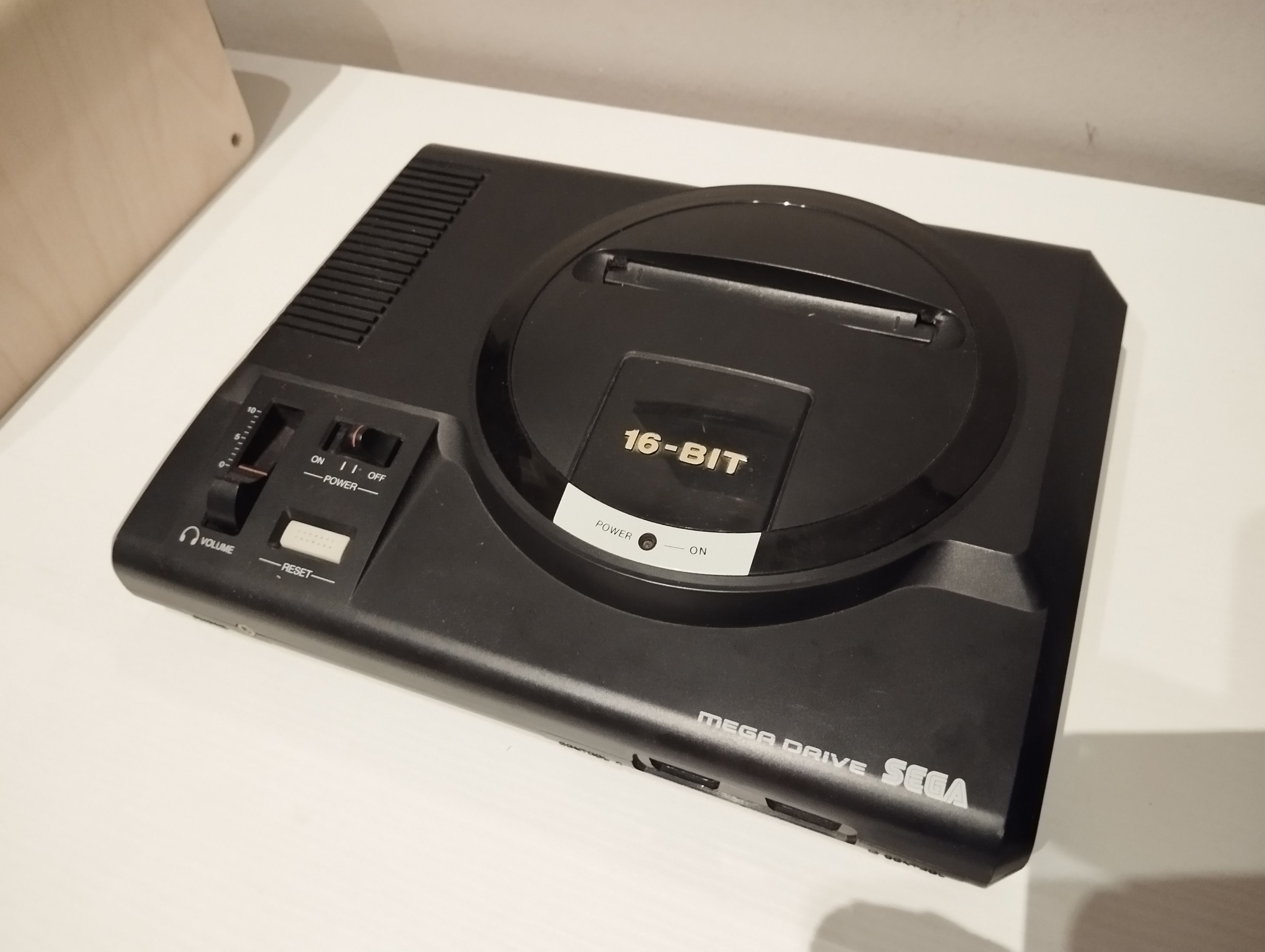
An european Model 1#
In short, analog TV systems of the past would work at different frame rates and resolutions. PAL, used mostly in Europe, would run at 50Hz, with slightly higher vertical resolution (625 lines). NTSC runs at 60Hz, with lesser vertical resolution (525 lines). Color was also encoded in a different manner depending on the standard, modulated within a subcarrier signal of varying frequency and meaning. PAL is considered by most to have a superior color encoding. Analog video is a huge and interesting topic by itself, and we won’t be going into greater detail here.
The framerate difference is quite significant. Most games of this era use integer frame timers for gameplay control, and it is usually hard to adapt all of it so that the game plays the same on 83% of the framerate. As a result, most games are not optimized for PAL. The first Sonic the Hedgehog is a particularly egregious example of this. Even the music is slower on this one. At least the later titles adjusted the music playback, but the gameplay is still 12% slower. So, it is very desirable to be able to run your unit with NTSC settings, at 60 Hz, and that’s basically the main motivator for modding a PAL Mega Drive like this.
Frame rate aside, the PAL format has one advantage over NTSC: increased resolution. There are more vertical lines for display, and if the game is optimized for PAL, it can display an additional 16 pixels of vertical resolution. If the game is not, though, it will just display larger top and bottom borders, squishing the overall image. For example, this is how Mortal Kombat looks in my TV set:

Mortal Kombat 1 borders. Ugh.#
So, the PAL resolution advantage is there, but since many many games disregard it entirely (most of them?), it just translates to a worse experience. Another motivator for modding the console.
In this post we’ll use the term format for the TV system setting (PAL, NTSC), and we use the term language to refer to the two possible internal language settings that the console can have. Here is a table with the main regions and their respective settings:
Region |
Format setting |
Language setting |
|---|---|---|
U.S.A. |
NTSC (60 Hz) |
English |
Europe, Australia |
PAL (50 Hz) |
English |
Japan |
NTSC (60 Hz) |
Japanese |
Brazil |
NTSC (60 Hz)* |
English |
Note
In Brazil, the TV system was actually PAL-M, which is basically NTSC’s timings and resolution, with PAL’s color encoding, so the composite signal encoder has differences. But as far as the rest of the system is concerned, it is NTSC.
Higher NTSC frequency with PAL color encoding? Huh, we had the best of both worlds, really.
The language setting can be used by games for region locking, just as well as implementing multi-language ROMs. But besides that, it does not change much about the system itself, so we’ll focus on the video format aspect. Note that we’ll be focusing on the model 1 (excluding revision VA7, which is basically a model 2 inside a model 1 shell), so some things may not be accurate or not apply to later models.
A Look at the Board#
Taking out the motherboard, we can see how these settings are accomplished in practice.

The main circuit board of the unit. The region settings and main oscillator are zoomed in.#
The jumpers are quite straightforward. The language signal at the top is typically permanently connected to 5 volts or ground, indicating if games should present themselves in english or japanese. The format signal at the bottom is also brought high or low, to signal whether the console should output video in the PAL or NTSC format.
In the case of this board revision, the jumpers are a bit hard to see under the silkscreen, but they are there. Yes, they not actual wires, but are printed as part of the circuit board itself. This was likely to save production costs. So for modification, the PCB traces themselves need to be cut off.
The main oscillator demands a deeper look. It is the main clock source for the system, and the oscillator value varies according to the originally intended format. In this case, for PAL systems, its value is 53.203 MHz. It is used to derive other clock signals, and how this is done depends on the format setting of the jumpers as well. Let’s discuss it in the next section.
Clocks and Timings#
There are three main clock signals. A master clock, the CPU clock (also used for FM synth), and the chroma subcarrier clock.

Clocks diagram (simplified)#
A fixed oscillator generates a master clock for the entire system. This master clock is used by the console’s VDP (video display processor) to generate its internal clocks, and via clock division, all of the other clocks used by other components of the system. The values of the master clock and derived clocks vary according to the console’s format, like this:
NTSC |
PAL |
|
|---|---|---|
Master Clock |
53.6931 Mhz |
53.203 Mhz |
CPU clock divider |
7 |
7 |
CPU frequency |
7.6704 Mhz |
7.6004 Mhz |
Chroma subcarrier clock divider |
15 |
12 |
Chroma subcarrier frequency |
3.57954 Mhz |
4.433583 Mhz |
Existing Modifications#
After looking around for a way to mod my unit for 60 Hz, I ended up finding these three kinds of mod are the standard way to go. Let’s review what people usually do.
Simple region switch#
A simple physical switch is used to change the format line signal. Can also be done for language the same way. This is easy to implement, and frequently done. However, it usually demands drilling a hole in the case, and the unit ends up with extra hardware hanging from the outside. Not the prettiest solution, but it sure works.
It must be noted that when performing such a mod, the master clock remains unchanged, regardless of the selected format, so every clock is slightly out of spec.
NTSC (modded) |
PAL (modded) |
|
|---|---|---|
Master Clock |
53.203 Mhz |
53.6931 Mhz |
CPU clock divider |
7 |
7 |
CPU frequency |
7.6004 Mhz |
7.6704 Mhz |
Chroma subcarrier clock divider |
15 |
12 |
Chroma subcarrier frequency |
3.54687 Mhz |
4.474425 Mhz |
Multiplier from on-spec values |
99,08 % (slower) |
100,9 % (faster) |
This one-percent difference may seem small, as it is, but for the chroma subcarrier, it can be a big deal. Even when they can handle weird sync durations, many TVs show a black and white signal when the region is switched, because they cannot identify the chroma subcarrier anymore, and just display color artifacts, or a purely black and white image. For a PAL model, it is customary to use an RGB SCART cable to get the video, bypassing the composite encoding entirely, so this may not be much of an issue.
Switchless region mods#
This kind of mod uses a microcontroller to allow for format control (and sometimes language control) without needing to add external hardware or drill holes in the case. The timing differences outlined for the simple switch mod also apply here.
It usually takes control of the reset line and adds a bypass for the reset button. This allows the reset button to be used as the main interface for switching regions. A short press does a normal reset, and a long press selects another region setting. This can also be used to ensure the system is properly reset when the region is changed.
I don’t know what actually happens if a reset is not done. I read that games usually crash? Maybe we’ll see…
Some mods also read controller input to allow switching regions without getting up from the couch. Finally, the versions I’ve seen tend to replace the power LED with an RGB one, and change the power LED color depending on the currently selected region. I don’t want that, though…
DFO (Dual Frequency Oscillator)#
This mod replaces the built-in master-clock oscillator with a programmable oscillator, that changes frequencies according to the selected format. When combined with region switching (usually the case), a fully multi-region Mega Drive with accurate timings is achieved. This can be bought off-the-shelf, but can be expensive. It can work independently from other mods, receiving only the format signal as the only input. Therefore, it can be installed later if inaccurate timings are an too much of an issue.
Making my Own Mod#
Sure, I’d love to do all of the above and have a fully modded console, with multiple regions and accurate timings. But I need to prioritize what do first.
Since I’m going to use an RGB scart cable later, that will bypass the composite signal encoder, so the chroma subcarrier frequency does not matter in this case. And since the DFO mod requires hardware I don’t have, and can be installed independently, I’m skipping it for now. The final timings are going to be inaccurate, at least at first, but should be good enough for a first iteration.
I also don’t want any external, visible modifications, or additional hardware switches. So I’m going for a switchless region mod at first. And while we’re at it, maybe we could try bypassing the power LED circuit as well, and reuse it, because once again, no externally visible modifications. We don’t need an RGB LED.
For this project, I chose the Raspberry Pi Pico W. Why?
first and foremost, I have one lying around;
widely available;
relatively powerful without being too expensive;
in the future we could make use of WiFi and/or Bluetooth, opening up quite a few possibilities:
Allow connection of wireless bluetooth controllers. Imagine using the programmable IO block to implement an internal controller peripheral. Now that would be pretty amazing.
Do the same as the above, but with a bluetooth mouse. That’d be perfect for my current game project.
Updating the firmware without having to open up the console.
Control region and language settings wirelessly, without messing with the reset button. An overkill, but possible.
Ok, let’s not get too carried away, back to reality. So, how are we going about this?
The wiring of the signals is not going to be much different from other switchless mods. Using the original power LED is perhaps the most significant difference. We can avoid modifying the original PCB for this because we can just connect the original power LED to the mod directly. But it is just an LED.
Other switchless mods allow resetting via the controllers by reading signals from their IO ports directly, but we can skip this for now. So, here is a table with the full pinout:
Name |
Function |
Description |
|---|---|---|
+5V |
Power rail |
- |
GND |
Ground |
- |
Reset button |
Input from the bypassed reset button |
Will be connected to ground when pressed, floating otherwise. An input with a pullup can read its state. |
Reset signal |
Resets the console, via the IO controller chip. |
Needs to be floating when not asserted, and grounded otherwise, just like the original button did. Switching from an input to an open-collector output set to ground does the job. |
Language signal |
Either 5V or 0V |
A simple output does the job the jumpers used to do. |
Format signal |
Either 5V or 0V |
Same, a simple output does the job the jumpers used to do. |
Power LED signal |
Either 5V or 0V |
Powers the power LED. Needs a resistor across it to not burn it. Original schematics read 120ohm, I used 220ohm because it’s what I’ve got, and it looks just as bright. |
Power LED ground |
Ground |
Just for convenience, we don’t need to solder the power LED ground to the board, this keeps the cable neater. |
Now that we have the signals and how they should behave, it was time to lay down how the setup should look like, what to cut, where to solder, etc. Based on other install guides and a printout of the PCB copper, I laid out this simple diagram on inkscape:
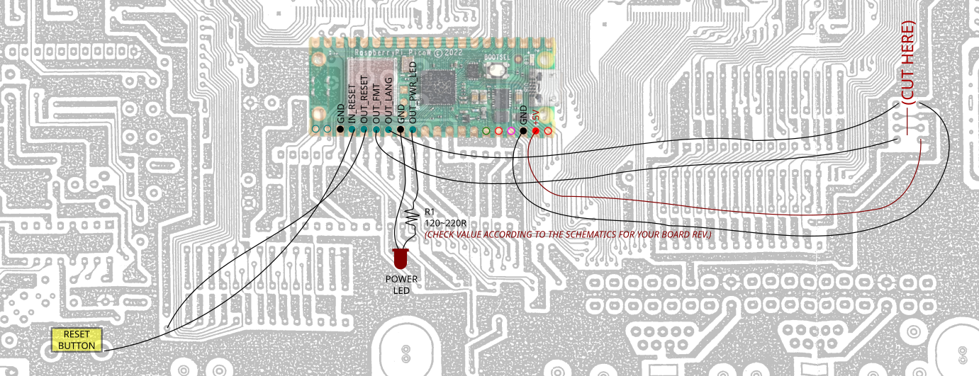
Install diagram. Pico is to scale. Board pinout was used as a reference.#
(Here’s the full image, with the reset button trace location).
Then, it was time to code. I used the Arduino runtime for a quick and dirty implementation. I ended up with the following behavior:
Always start on US region by default.
When RESET is held down for a bit, it changes the desired region, without applying it, and blinks the power LED to indicate the current selection.
When RESET button is pressed quickly, it applies the current region selection and resets the system.
That’s all there was to it. To aid in implementation and testing, I built a simple prototype on a breadboard, to show me all the signals and provide the reset button, before doing anything to the Mega Drive PCB. This is what that looked like:
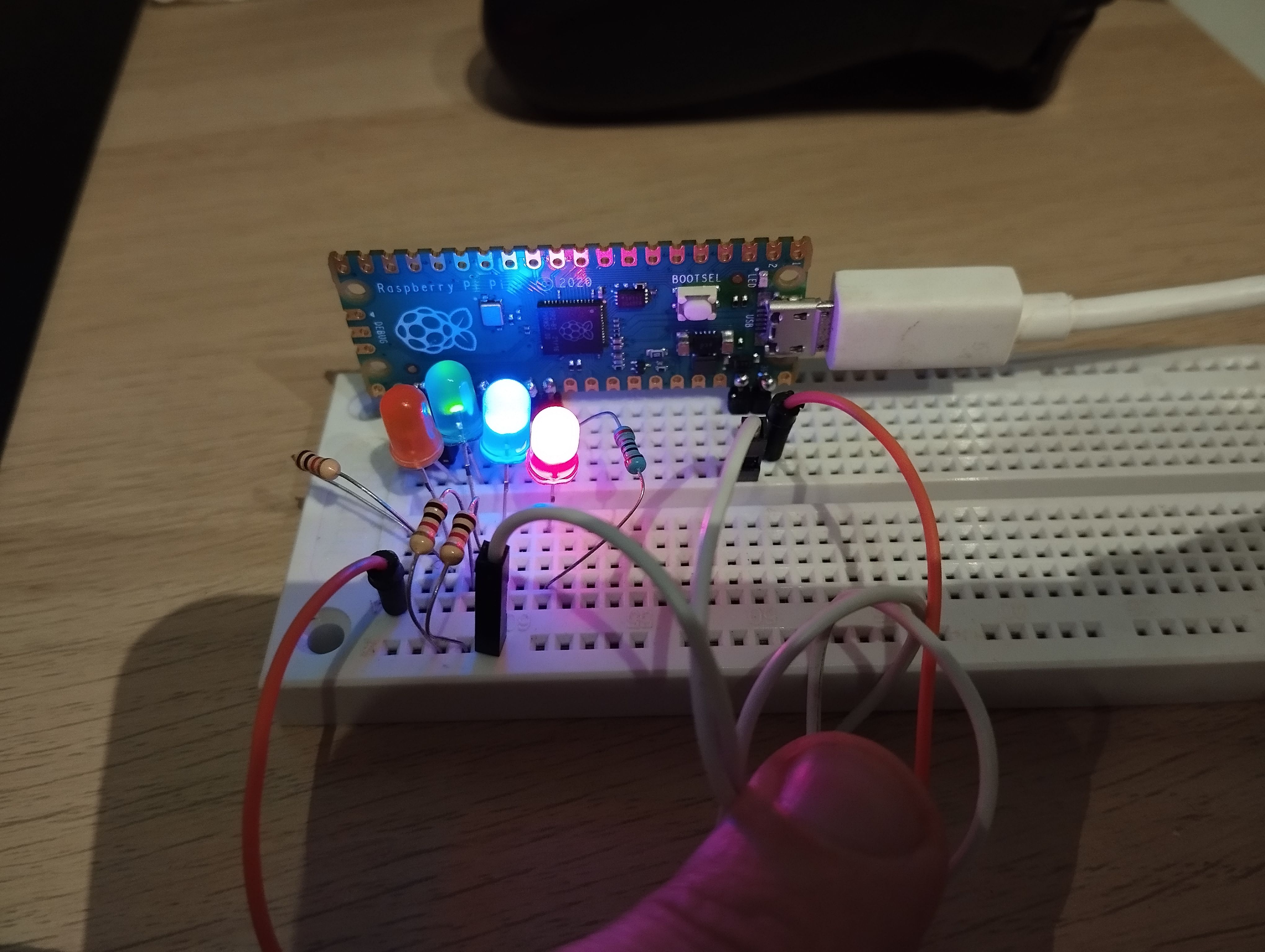
Breadboard that helped me figure out the firmware.#
After the code was done, and behavior seemed to be what I wanted, it was time to install it. All the signals were soldered using female Dupont wires. A male pin header was installed in the microcontroller, and all the signals were connected to it like this. A simple cable, with an embedded resistor, was made for the power LED, with protective heatshrink. The cable itself has female Dupont termination on both ends, and connects the Pico with the LED directly. Finally, I decided to install it atop the RF shield with some velcro on the back, to raise it from the grounded metal shielding, and to provide an easy way to remove/replace the Pico if needed. It was also important for it to be outside the shielding when the time came to use the wireless functionality of the Pico W.
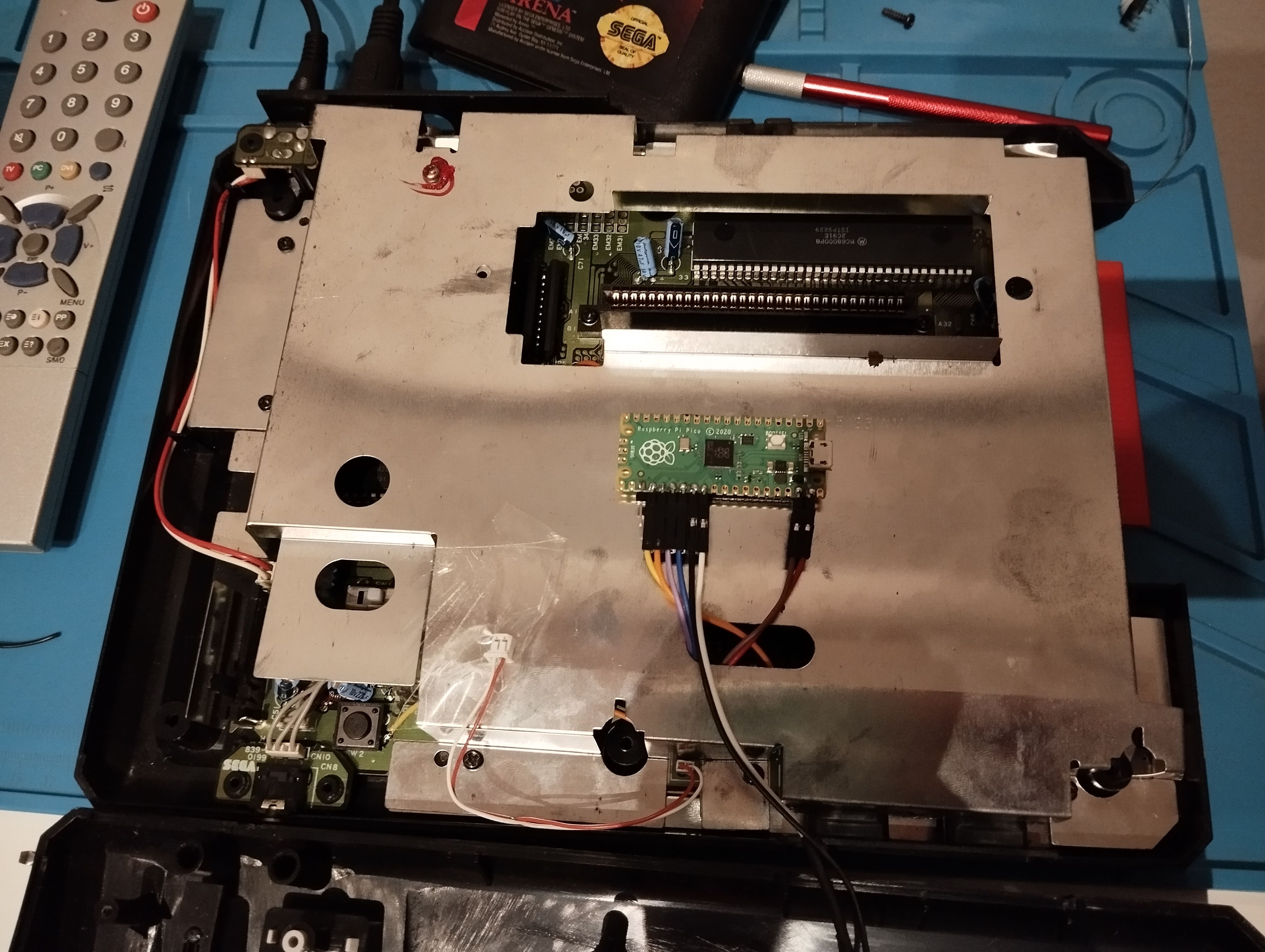
How the mod looks like after installation.#
Here’s what it ended up looking inside the machine. I’m happy to report, even with how simple it is, it just worked as intended, on the first try. I can change the region, and the machine looks unchanged from the outside. What a sigh of relief that was. And then I just smiled.
Project files and installation#
The developed firmware is available here. This post is not meant to be an install guide, although the repo contains an example diagram. Alongside install guides for other mods, you should have all the required information available for installation. Just remember this mostly applies to a Model 1 (Non-VA 7). I don’t know much about later models and revisions, this may not be possible on more consolidated revisions (like the Genesis 3), but the principles are the same.
I want to return to this project to implement the wireless stuff I dream of, at some point. I’m looking at Bluepad32 as the joystick host solution, that already supports a wide variety of controllers, and just recently added support for the Pico W. OTA via wireless was already implemented but is subject to change. As it is now, the mod is basically the same as other switchless mods, only with an RPi Pico instead of a PIC or ATmega.
And before I forget, I had to name the thing. So this mod is called… megaPALadin. Trademark.
References and Links#
Why is Sonic Faster in America? NTSC vs PAL/60Hz vs 50Hz | Nostalgia Nerd - Nice introduction of the issue at hand. By NostalgiaNerd, via YouTube.
Sega Mega Drive Switchless Region Mod Install Guide - Install documentation for a commercially available swictchless mod. By Consoles Unleashed.
Sega Mega Drive Dual Frequency Oscillator Install Guide - Install documentation for a commercially available DFO mod. By Consoles Unleashed.
SEGA Mega Drive (model 1) PAL/NTSC switching - An example of a simple switch mod by John Tsiombikas
A new mod for Mega Drive 60Hz colour correction - A way to restore the composite chroma carrier, after simple format modding, using an external clock divider. By “static-void”, via WaybackMachine.